The A24- Details of Construction
This is a long post… I kept a lot of notes on this project because on occasion, I had to set it aside to work on other stuff. No biggie. Each step of the build had its own set of concerns. So I broke it down into several discreet sub-assemblies.
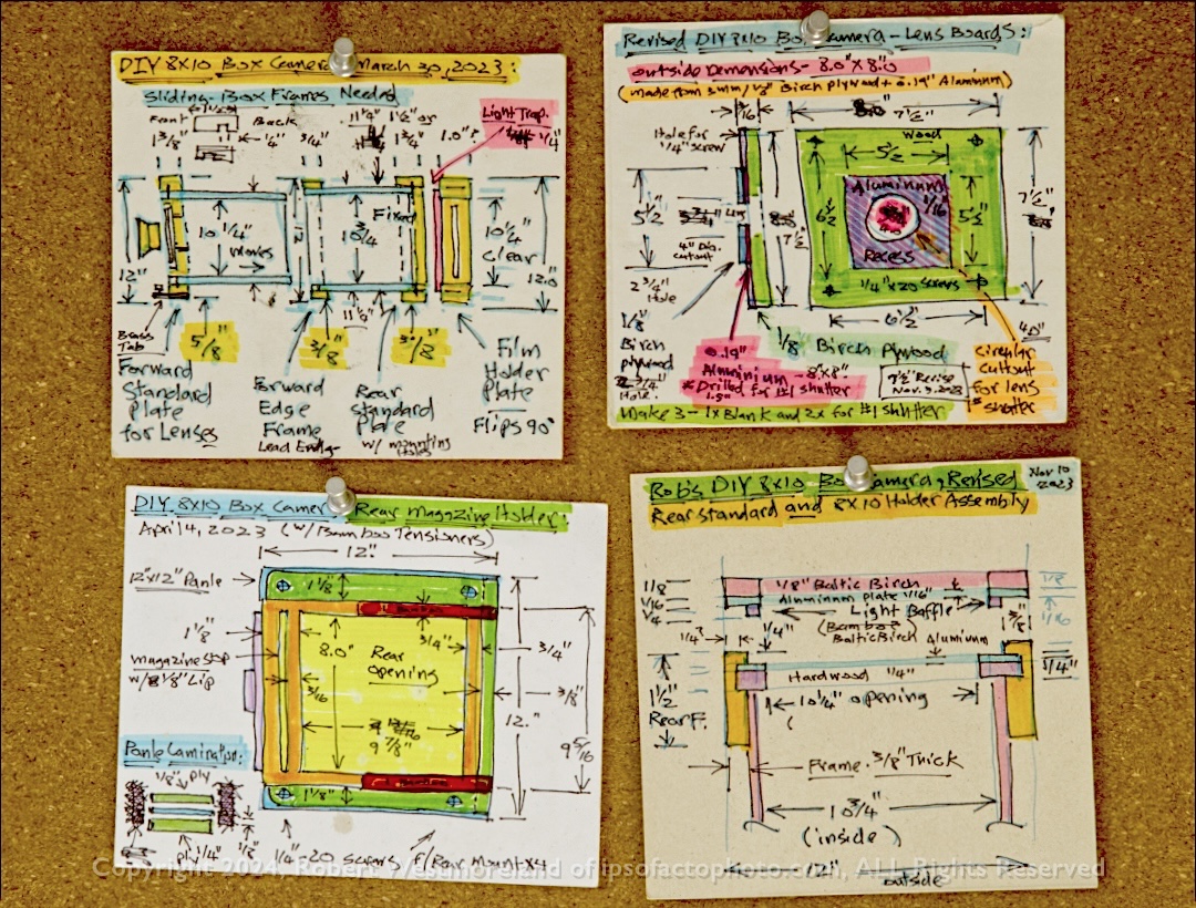 Four sketches from dozens more
A 3-in-1 Multipurpose Table Saw Sled
But before I could jump into all that, I needed to make a special sled for the table saw. Adding a hardwood dado edge to 5mm plywood is not something I could guess at.
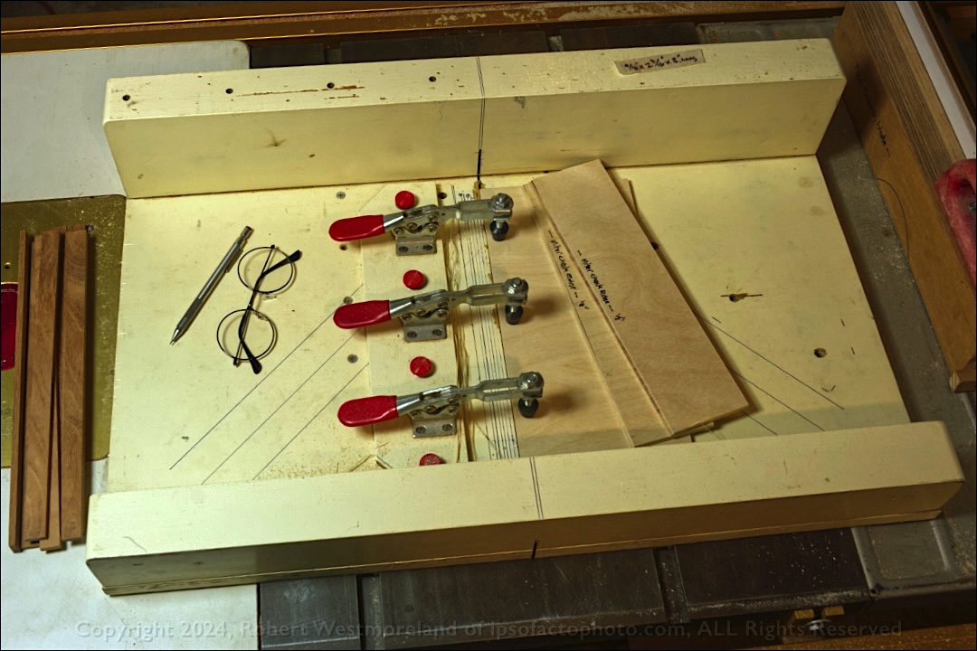 Full view of ‘3-in-1’ table-saw sled with removable clamp bar
The sled was assembled from scrap-wood from earlier projects. Several years later, it still works great. For the record, I did change out the saw blade and install a new drive-belt. It runs much smoother now.
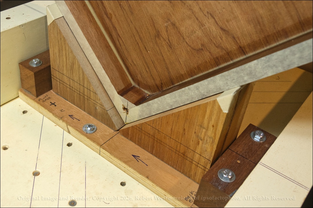 Corner dado slotting attachment for sled, A24 Base Frame view
The Nested Box and Hardwood Frames
My first thought was to make the nesting box set, out of a laminate of 1/8th inch (3mm) Baltic Birch Plywood and 1/4th inch (5mm) black foam-board so as to keep it light, but ridged. I experimented with bonding the two surfaces together with thin, slow-set epoxy under weighted pressure over several days, but it still warped. So I went with Plan B, a box panel of 5mm Baltic Birch with a dadoed hardwood edge. I used slow-set epoxy for most of the build.
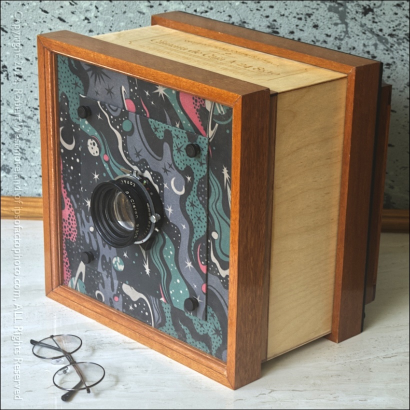 Hardwood frame assemblies with nested boxes attached, in closed position
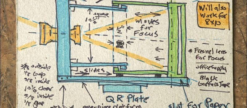
Outside frame dimensions were dictated by the fact that the camera would need to accommodate both vertical and horizontal views at 8×10. So 10” square, plus a 1/4” for inside panel clearance, plus the two wall thicknesses of 5mm each, PLUS an additional 2mm x2 for the space between the box halves. To minimize light-leaks, there is 8mm wide black velvet edging attached to the outside lead edge of the black box.
Overall, the Baltic Birch box is 12”x12” to the outside. The front and rear hardwood frames add another 3/8ths x2. That makes the hardwood frames just under 12.75”x12.75” to the outside.
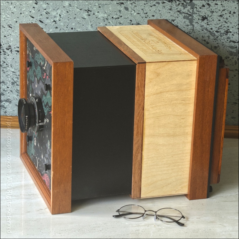 Hardwood frames with nested boxes formally attached, fully extended
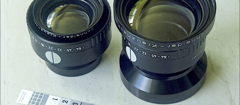
The measurement for ‘max focus travel’ was based on the minimum needed to achieve infinity on the 210mm lens versus the distance to achieve infinity on the 305mml lens with a ‘fudge factor’ of no more than 5 or 6 mm to either side. Minus the 8-9mm I would loose to the nested-box light seal. Have I lost you yet? (The factory verified focal-lengths are actually 208.4mm and 308.0mm, respectively.)
In the end, I was able to retain 120mm of internal travel, minus the nested box halves overlap.
Point of reference: In order to keep things as square and as true as possible, I scored a 24”x24” piece of a flat, glazed ceramic tile to serve as a flat work surface. A glossy one with no texture. To verify it was flat or ‘true’, I turned a stainless steel ruler on its edge to check ‘flatness’. All assembly was done on it… sometimes I would tape a piece of goldenrod (a coated paper) to the top if I was doing any epoxy work.
Step one- Assemble the two critical geometric planes from hardwood frames that match each other in size and form.
That being the ‘Lens Plane’ and ‘Rear Film Plane’ with removable sub components like the front ‘Lens Boards’ and rear ‘Film Holder’ (with matching ‘Removable Ground Glass Panel’). Because the rear Film Holder is removable, it can be set to 3 out of 4 positions; Left, or right side magazine insertion and ‘from the top’ for portrait.
 Finished hardwood frame assemblies ready for plywood nesting boxes, with removable Film Holder, Ground Glass Focusing frame, mounted and unmounted Lens Boards and an 8×10 Magazine
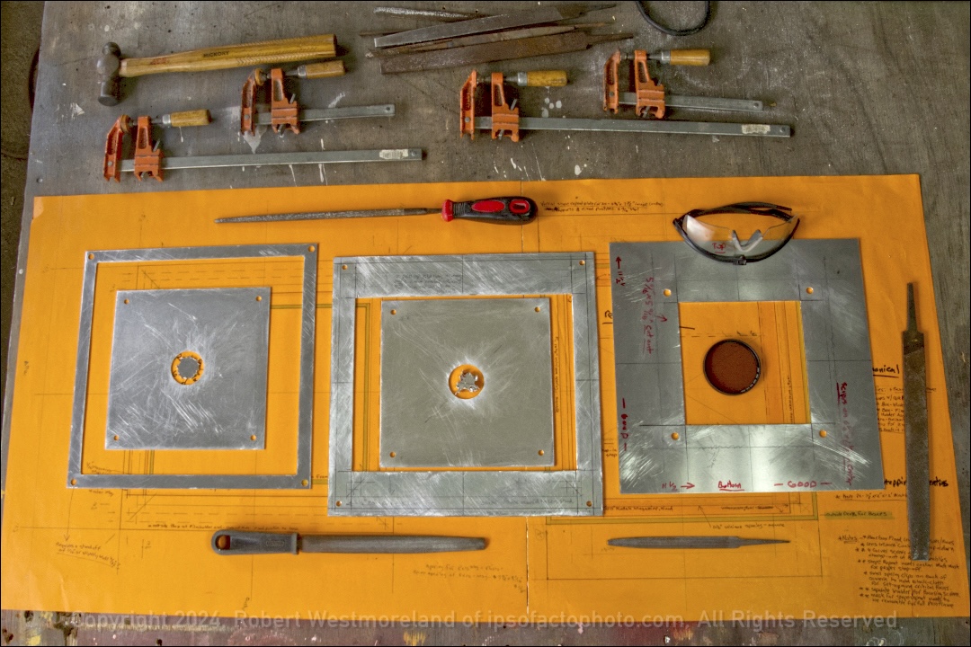 Aluminum stiffeners used to secure set-screw-inserts, prior to lamination
The Font and Rear ‘Standards’ or Frames- Once I defined the outside dimensions, I could proceed with making the hardwood frames and aluminum stiffeners that would support the lens board and film magazine holder.
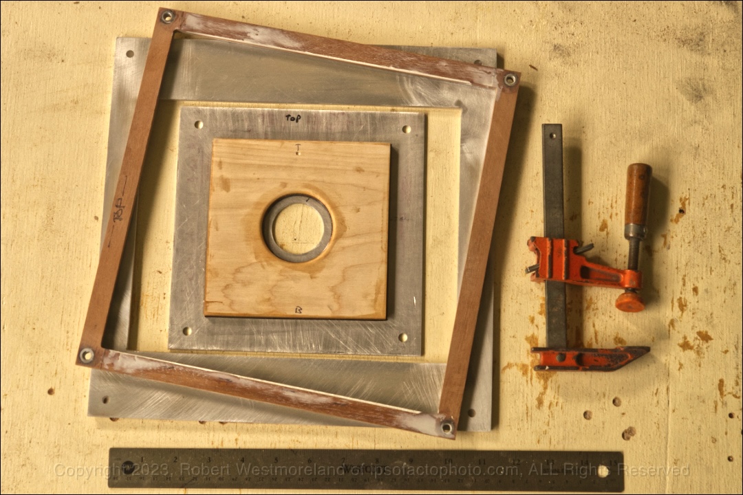 Aluminum stiffeners with screw-sets at the outside corners, after addition of hardwood furniture, black Nylon knurled screws were used
Because I needed to keep the ‘lens and film-plane’ as thin and flat as possible, they are a laminate of 1/16th inch Aluminum plate (scavenged from cut-down computer boxes) to 5mm Baltic Birch plywood. I did this to minimize any loss of focus travel and to accommodate 1/4-20 screw insets for mounting lenses to the front and the removable magazine holder at the rear.
 Front Standard components with fabric glued to aluminum pieces ready for frame miter, fit & assembly
Step two- The Nested Box Assemblies-
To assemble the Nesting Box Panels, I used a set of 90º corner clamps. Then cemented them to their respective Hardwood Frame Assemblies.
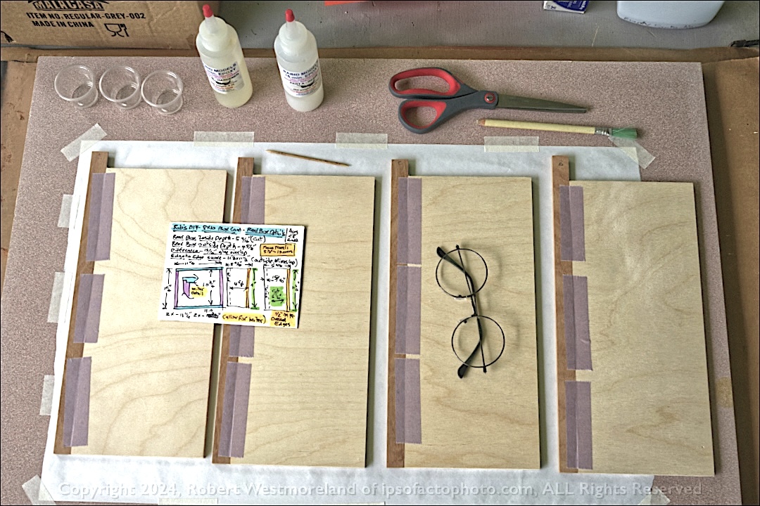 Box panels with dadoed hardwood strips, ready for epoxy
Before I epoxied it together, I did double-check my math again, as it relates to the ‘Lens Plane’ to ‘Film Plane’, one more time! I did that by crudely fabricating a cardboard ‘panels’ of the same dimensions, then taping it together long enough to actually run a few exposure/focus tests. I used old AGFA® photo-paper instead of film, for this.
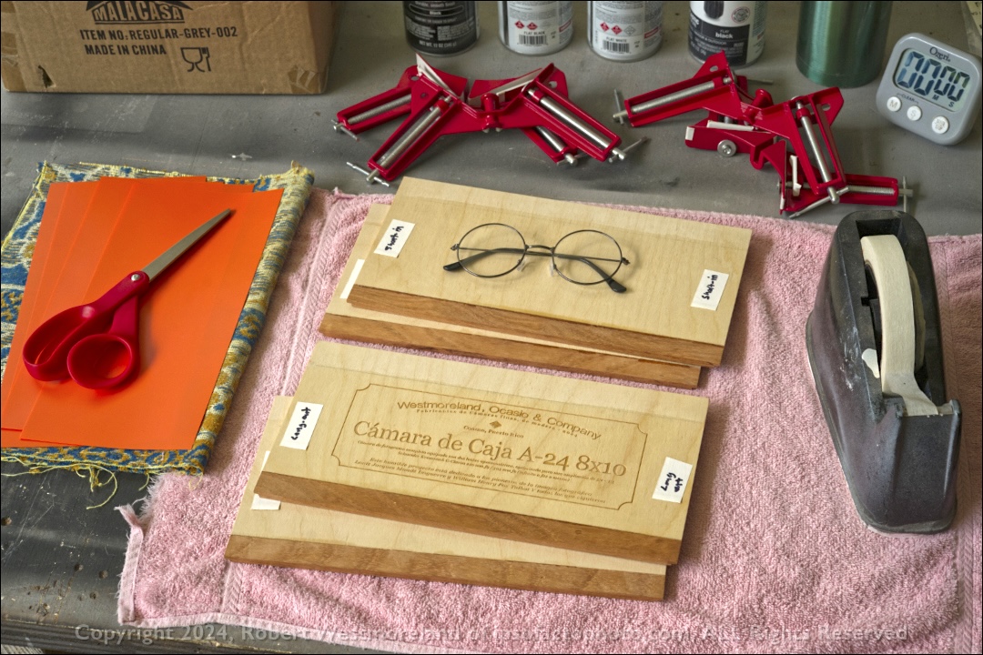 Nested Box Panels ready for assembly
I did achieve infinity focus with both lenses, but I’m at the end-of-the-road for the 305mm F9 lens. Later, I’ll fabricate an extension attachment so as to extend its close-focus ability when shooting still-life inside.
Box panels were assembled from 5mm Baltic Birch plywood, with mitered hardwood trim and mitered box edges. The inside face was spray painted statin black, then a final layer of matte black, before assembly.
Step Three- Focusing Rail Assembly and attachment-
This is something I agonized over- How to ‘incorporate a mechanism to provide smooth, but accurate focus’, with what I could score ‘off-the-shelf’. Most 8×10 box cameras simply slide back and forth on a wooden plate, relying on friction with a set-screw to hold focus, or use a geared brass rail with knob/gear drive mechanism.
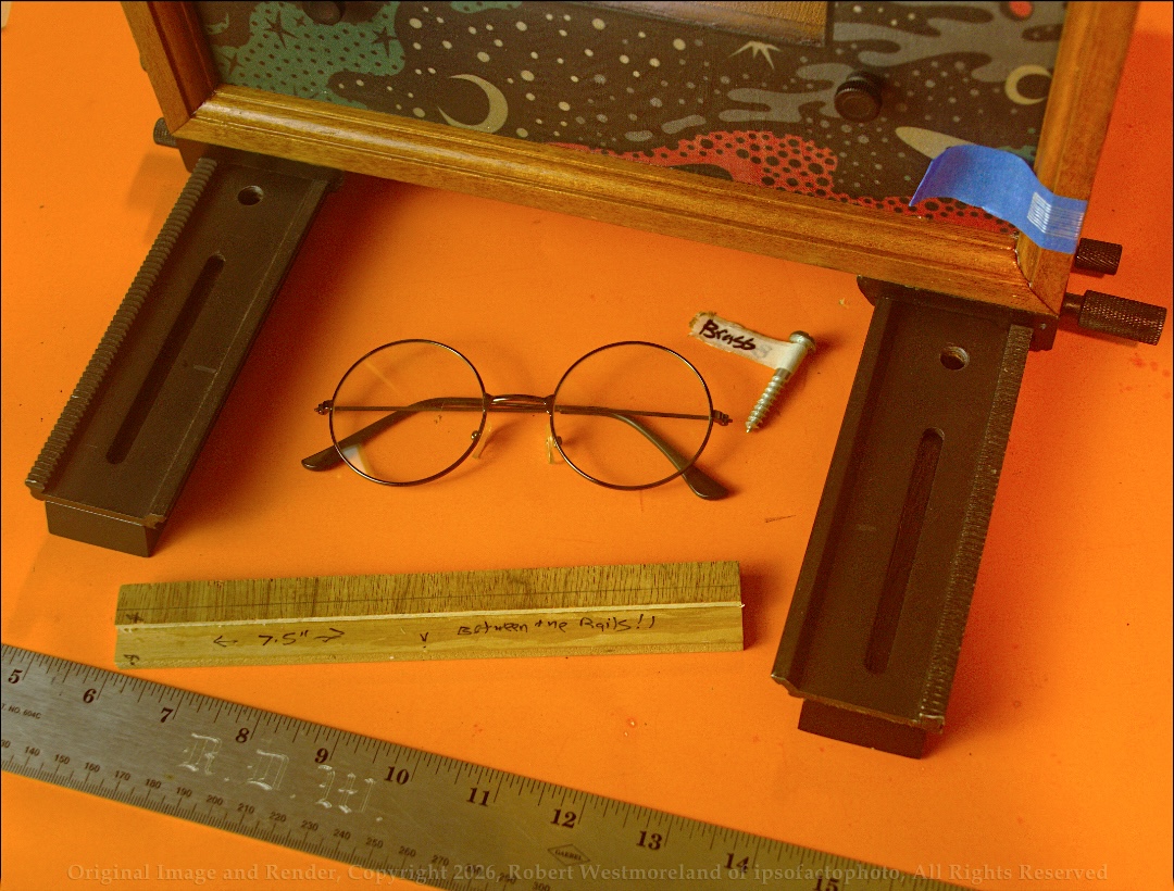 Aluminum Geared Rails, ready for Base Plate
I did consider making it out of milled, brass-geared-track, there was a source for that type of work. But going down that rabbit hole was well beyond my capability. Instead, I cobbled it together from a pair of aluminum macro rails normally used from a tripod or copy-stand. A more clunky approach, but within budget. Besides, it gives the finished article a more whimsical, ‘alt-retro’ look. The rails did require a short standoff from the deck-plate so one could get their fingers around the adjustment knobs.
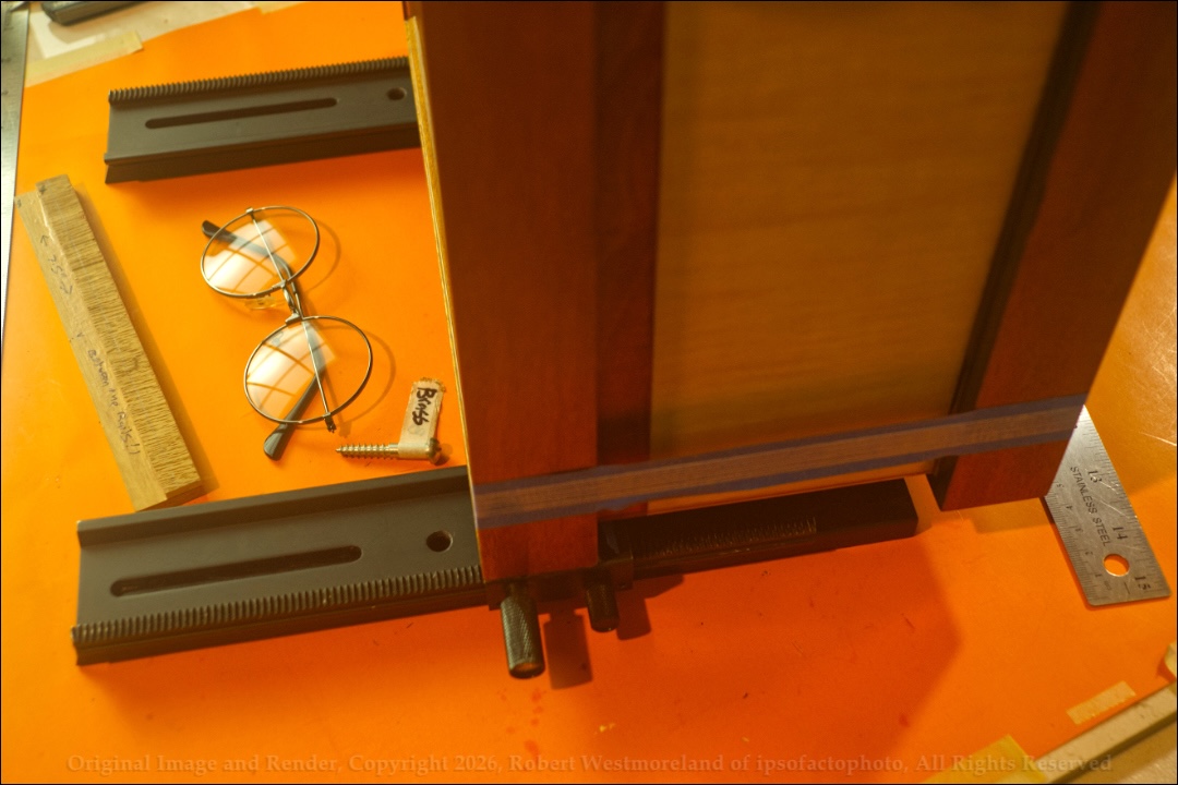 Front Standard attached to Aluminum Geared Rails, ready for Base Plate
I need to state that after having made this work, I would never use aluminum again. Biding was a problem I had to address. I did, It works, but making it out of brass would have been a much less stressful approach.
Step four- Base Frame and Top Plate
With all those components nailed down, I could now proceed with building the platform. In the end, the Base Plate Frame measures 15.5 inches wide by 16 inches long, to the oust-side. That left just enough room for a Baltic birch plywood box to drop over the top, secured to the base frame by 4 spring-latches. All sealed up, tight as a drum.
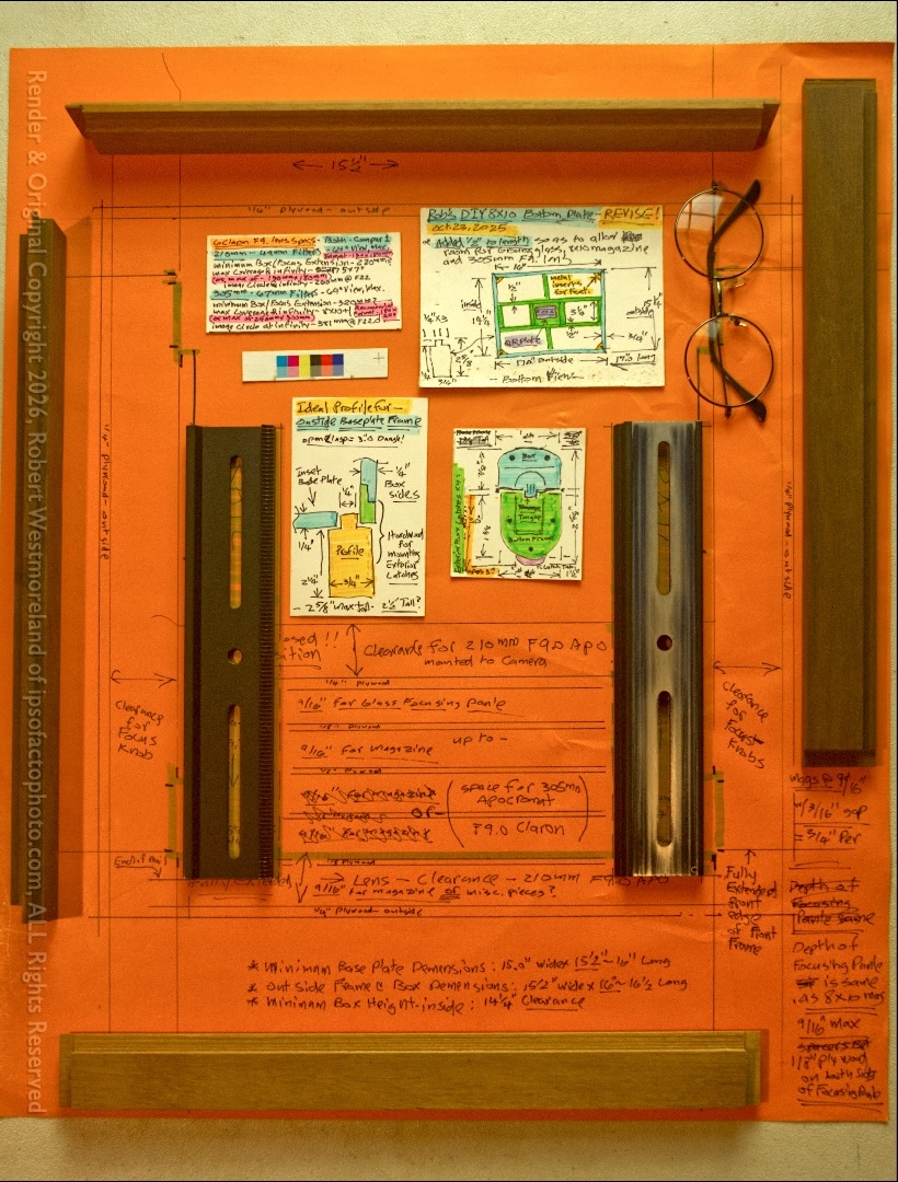 Key baseplate components and notes
The platform frame was made of scrap hardwood mitered at the corners and dadoed along both top edges. This was done to accommodate flush mounting of the top plywood plate and provided an outside lip for the Cover Box to rest in. Once the base frame pieces were epoxied together, the outside corners were slotted to take hardwood wedges. Trimming the wedges off after the epoxy set, did not go well and required a bit of ‘touchup.’ The Japanese pull-saw I used was rusted and kinked in several places. My impatience with this, only aggravated the problem. Nancy helped clean up the ‘rough spots’. My bad.
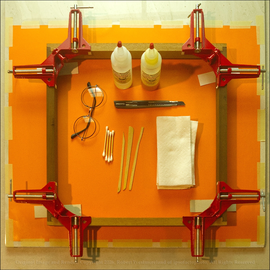 Assembly of Base Frame from dadoed and mitered pieces
The 3/8ths inch thick deck plate was also ‘a fix’. It was suppose to only be a 1/4th inch thick, but I forgot to take into account the table-saw blade thickness when I cut the inside dado. I was too far along with the base frame build to start over… not if I could make it work. I did try to score 3/8ths inch plywood veneer locally, but no go. So I laminated 1/8th inch Baltic Birch plywood to a 1/4th inch piece of premium South American plywood. That was done by working with slightly diluted wood glue, pressing them together with foiled parchment paper to the outside… resting on the 24 inch square reference tile, with 9 concrete blocks stacked on top. I let that set under pressure for 5 days before trimming it down to fit.
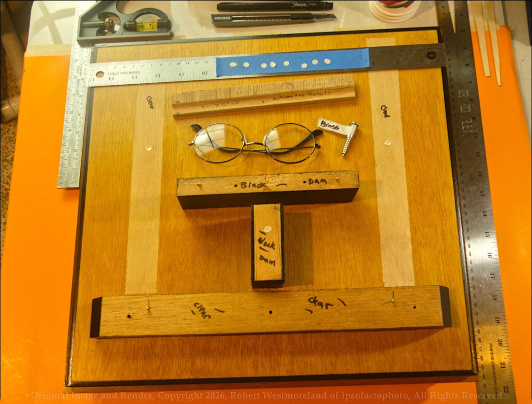 Top of Base Plate with standoffs in position, toothpicks for alignment
Triangle corner blocks were added to the inside corners of the frame for strength and to accommodate 4 metal- 1/4”-20 inserts for rubber feet… so it would never rest on a wet floor.
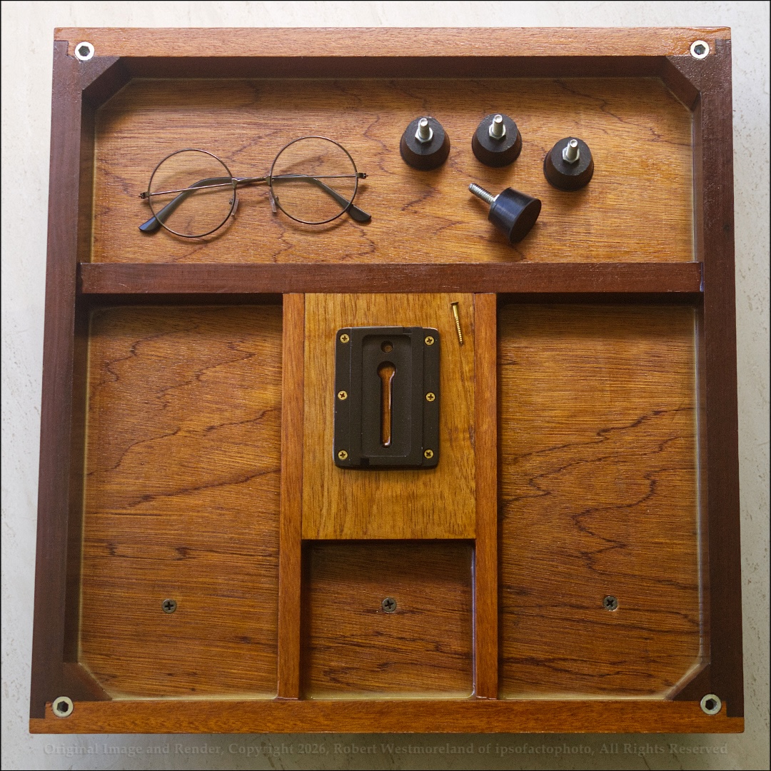 Finished Baseplate with tripod QR Plate and rubber feet prior to ‘fix’
After the plywood top-plate was epoxied to the outside frame, additional hardwood pieces were cut and mounted so as to reinforce the Aluminum ‘quick release’ (QR) plate. The QR plate is how it will mount to my tripod and helps distribute the weight across the entire frame assembly. The QR plate was epoxied and set in place with 6 brass screws.
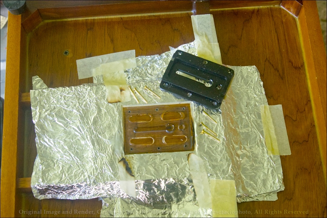 Wrong tripod QR Plate removed from bottom of Base Plate
Unfortunately, I used the WRONG QR plate!!
A bit latter I had to remove it and mount the correct one. I did that by covering the bottom frame assembly with several layers of foil reinforced parchment paper (for baking) leaving only the old QR plate visible. Which a little ‘judicious’ heat from a propane torch, I was able to soften the epoxy, screw out the brass screws and ‘tap-off’ the plate. After some cleanup, I added a 1/4” piece of plywood to address my mess, then mounted the correct QR plate with the same six brass screws. Not as pretty as the first pass, but just as strong.
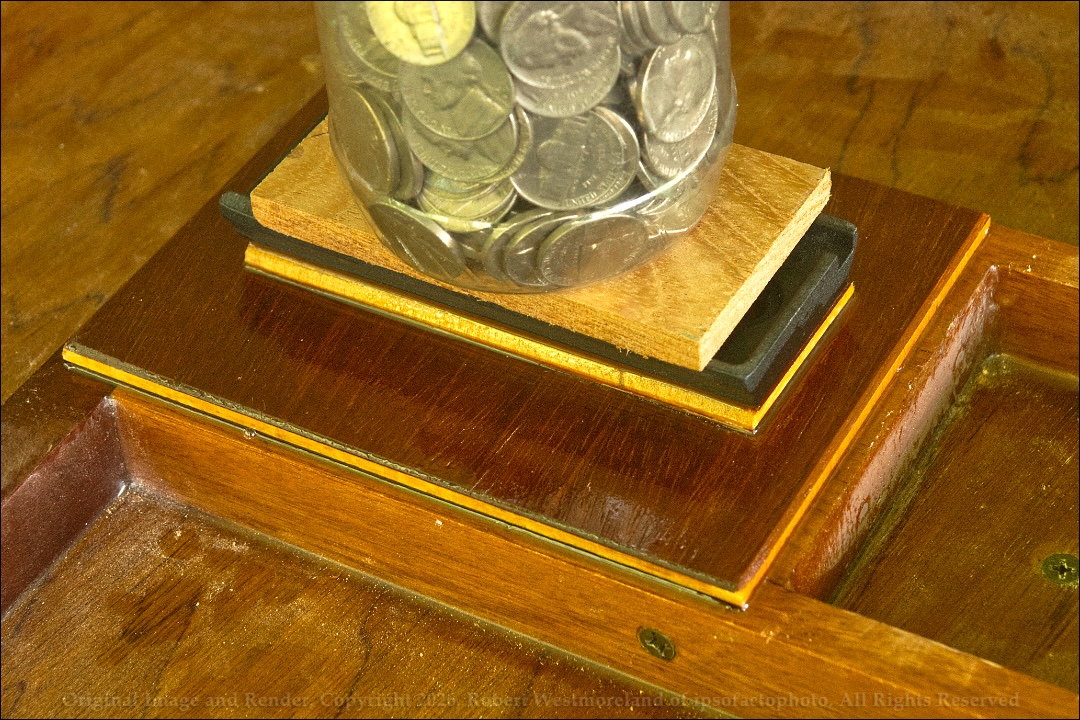 Correct tripod QR Plate installed to Base Plate Frame
The black hardwood blocks epoxied to the top of the plywood top plate (with screws from the bottom) are the standoffs needed to make it all work. Once all this was screwed and glued, I painted the entire top plate and frame with two coats of clear polyurethane. This should prevent any ‘comehen’, Puerto Rican termites, from attacking it.
Step five- Setting the nested box with aluminum rail assemblies to the plywood base plate
This was that last, most critical part of the build. I only had one shot at mating them together. Since this had to be set in place with epoxy, then brass screws, it had to line up perfectly the first time. I rehearsed this over and over before proceeding. Fit mattered most. Nancy assisted me with this…
I can say, we nailed it! There was a bit of adjustment made to the geared Aluminum rails, to smooth out its movement, but it functions as intended.
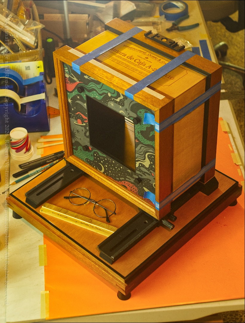 Box and Frame assembly on Aluminum Rails, secured to Base Plate
After setting the 2 wood screws to secure the aluminum rails to the base frame on the bottom, I could move on to setting the Focus Stop, which prevents me from running the focus adjustment past the end of the aluminum rails. That was made from a 90º metal bracket, painted black, with a little neoprene bumper pad.
 Detail of Aluminum Rail with Focus Stop
Other Critical Components
The Removable Magazine Holder– It also incorporates a piece of 1/16th inch aluminum plate to insure proper stiffness and durability. The magazine holder remains mounted to the rear standard for storage and is only removed to change orientation.
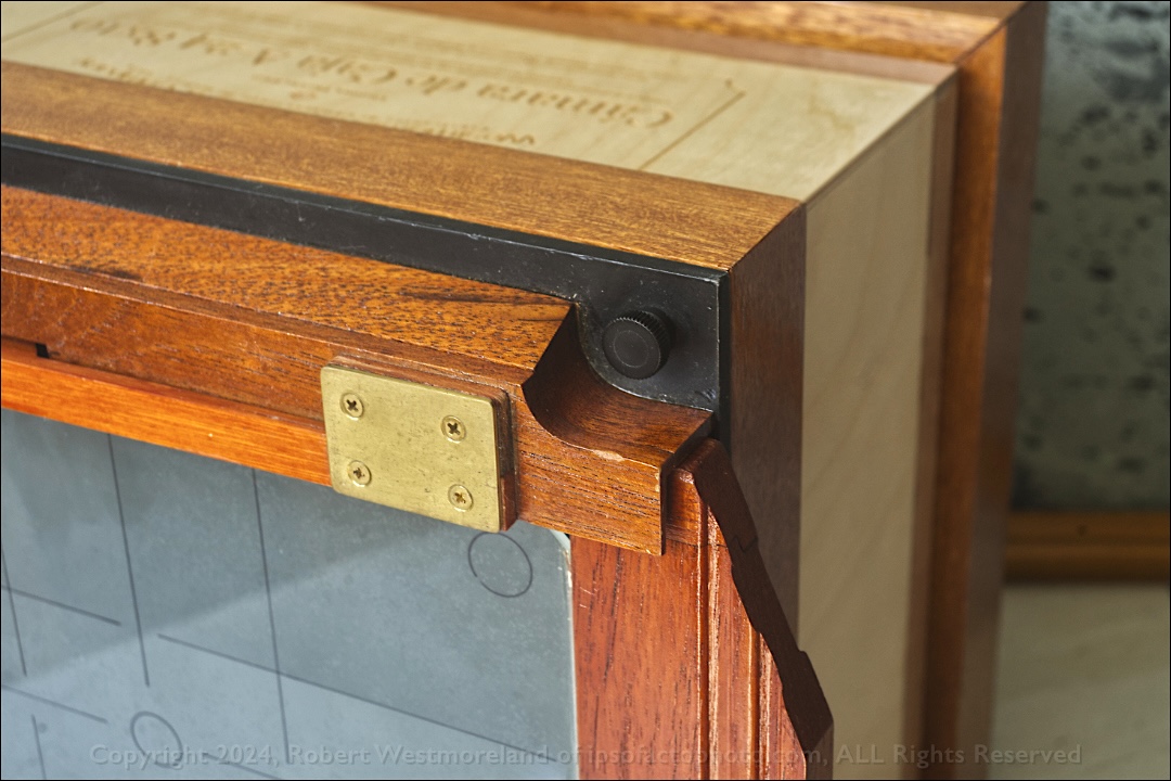 Magazine & Focusing Panel sub-assembly, corner screw detail
Most cameras of this type make that a spring-loaded affair that remains attached to the magazine holder, so the mag slides in ahead of the ground glass. My ground glass is mounted to a hardwood frame that is stored in the plywood Cover Box when not needed. (or will be)
 Laminated, Bamboo magazine retaining clips, after jigsaw cuts
Ground Glass Focus Panel- Most cameras of this type make that a spring-loaded affair that remains attached to the magazine holder, so the magazine slides in ahead of the ground glass. My ground glass is mounted to a hardwood frame that is stored in the plywood Cover Box when not needed. (or will be)
 Ground Glass Frame dimensions, with ground glass
This is a relatively critical component since the ground glass must match the dimensions and ‘focus point’ of a typical 8×10 magazine. I used marine grade silicone calk to ‘bed’ the ground glass to the same depth as an 8×10 magazine, minus the ‘dark-slide’. That’s why the ground-glass is not secured with metal clips, only via the adhesion of silicone. This should minimize ‘shock’ to the glass while in transit. An epoxy putty would have been more permanent, more stable, but more ‘shock-prone’.
Actual image composure and focus is done at the ground-glass with a 6x loupe. Keep in mind, the image on glass is upside-down and flipped sideways.
Minor Details
As can be seen in several shots, I also attached a two-slot Aluminum cold-plate to the top of the rear box frame. That allows for the attachment of a bubble-level and a simple plastic viewfinder or small light-meter… I have two plastic viewfinders. One marked ‘28MM’, a ‘wide view’ for the 210mm lens and another marked ‘35mm’ for a somewhat ‘normal view’ for the 305mm lens. These are crude little viewfinders at best.
The last issue was to make sure it was light tight… The overlap of the nested-boxes was done by bonding black synthetic velvet edging tape (8mm wide) to the back edge of the nesting front box, then adding a 2mm black foam gusset to the forward edge of the rear box. All good to go, I thought… I did discover additional light leaks around the area where the magazine slides in and out of the Magazine Holder assembly. So I stopped and dealt with that as well.
So No More Light-leaks!
The A24 8×10 Box Camera is good to go!
RDW